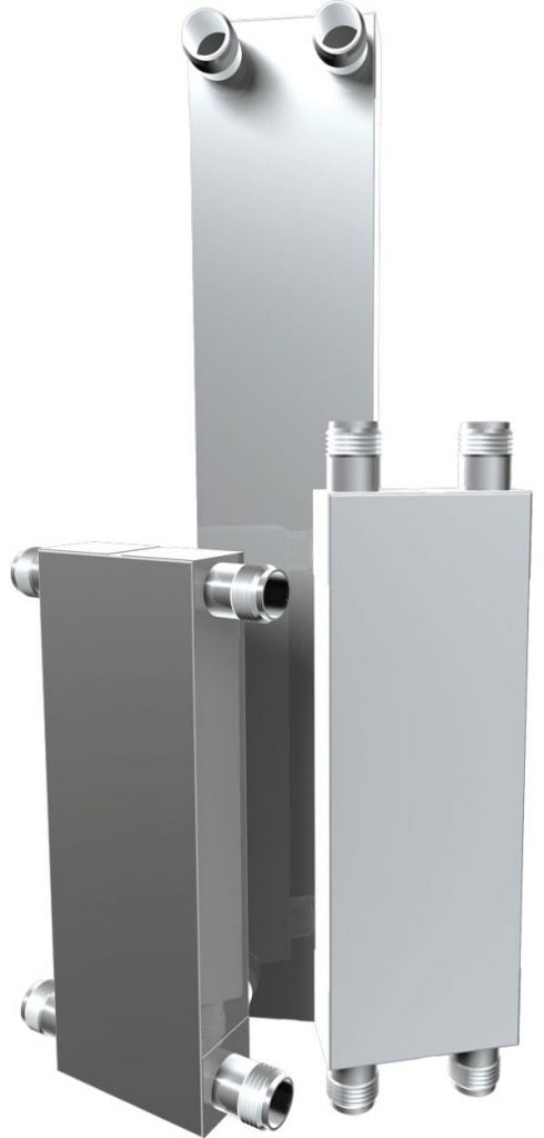
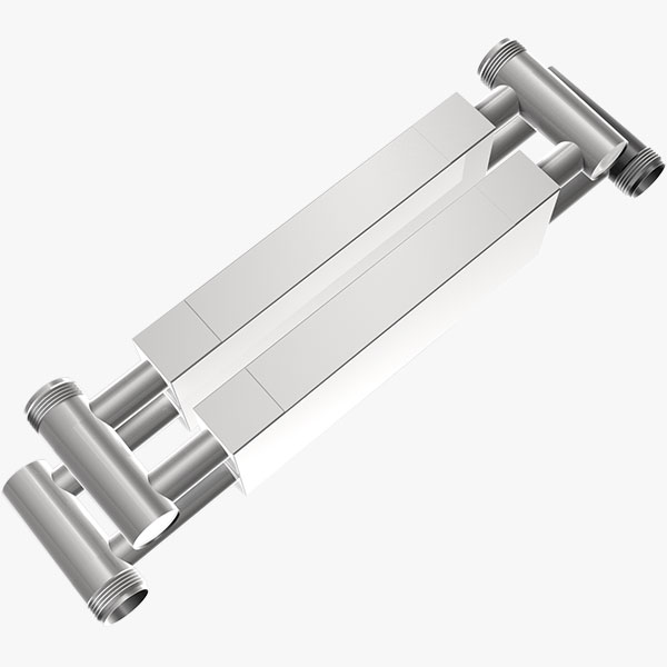
The MAXCHANGER® Mini-Welded Heat Exchanger standard materials are all-welded 316L SS or titanium. Its unique dimpled plates, combined with countercurrent flow, produce extremely high “U” or “K” values
High Performance
Shell & tube-class performance under demanding conditions, for a fraction of the installed mass and footprint
Tiny Footprint
Ultra-compact footprint enhanced by flexibility in nozzle positioning
Responsive And Efficient
Immediate thermal response and a close temperature approach capability of less than 1°C (2°F)

High Integrity
Withstands fatigue-type stresses induced by pressure cycling in steam heating applications
Superior Durability
Outstanding durability compared to CBE or S&T exchangers, often outliving the system service life, eliminating the need to design for service access and more added space.
Fouling Resistant
High turbulence prevents energy-robbing fouling or scaling, reducing maintenance burdens as well
Related Mini-Welded Applications
Related Mini-Welded Services
The MAXCHANGER is available in two plate lengths:
The number of plates used can vary depending upon the thermal duty. Both single- and multiple-pass configurations are available.
ASME Code stamped construction is available. In addition to the standard 316 Stainless Steel or Titanium, optional materials include Hastelloy, Alloy 20, SL6XN, Monel and Inconel.
Product Literature
General Mini-Welded Specification
| Pressure Rating: | 82.7 barg (1200 psig) |
| Temperature Rating: | 454°C (850°F) |
| Max. Connections: | 50 DIN (2 ANSI in.) |
| Max. Area Per Unit: | 4.1 m2 (44 ft2)a |
| Standard Plate Material: | 316 SS and Titanium |
| Standard Shell Material: | 316 SS and Titanium |
| Max. Differential Temperature: | 232°C (450°F) |

How The MAXCHANGER Mini-Welded Heat Exchanger Works
The 1-mm (0.039-in.) thick dimpled heat exchanger plates are sandwiched between top and bottom plates. Special spacers separate the plates, isolating the channels and establishing countercurrent flow. There are no gaskets. Four corner angles (or half-pipes) are welded to side plates, top and bottom plates and to the heat exchange plate points, forming inlet and outlet headers.
Inlets and outlets may be located on the sides, corners or ends for flexibility in tight spaces. Connections may be NPT or flanged, and mounting brackets or lugs may be specified.
